
Courtesy of the MIT Museum
While the history of computing is littered with controversial claims of firsts, it’s clear that the late 1940s and early 1950s saw a dramatic uptake of the basic ideas of electronic stored-program computing with many important developments.
One of these developments took place at MIT with the building of a machine called Whirlwind. Funded by the Office of Naval Research and the US Air Force, Whirlwind was a large-scale digital machine that was among the first to tackle the use of high-throughput calculation for real-time problems like aircraft simulation and air traffic control.
This vacuum-tube computer was first brought online at the end of 1949, with continuing development for several more years. Whirlwind was a one-of-a-kind research machine, and although only one was ever built, it had an important influence on many subsequent systems, most directly on the SAGE AN/FSQ-7 Air Defense computer.
Although much of Whirlwind was lost when the machine was decommissioned, the Computer History Museum (CHM) and the MIT Museum retain many of the machine’s components, some of which are on display in CHM’s permanent exhibition, Revolution: The First 2000 Years of Computing. This essay places the pieces on display in the context of the overall, original computer.
Despite its early date, Whirlwind’s designers used concepts that are still very familiar to current computer designers (although now found in $25 machines like the Arduino, rather than research machines costing over $3 million in 1950-dollars!). Some of the points that could have gone on a Whirlwind data sheet include:
Whirlwind’s computing architecture is lean but not unfamiliar. The machine had a couple of 16-bit registers, a 16-bit add/subtract unit, and a hardware multiplier/divider, all organized around a single, uniform 2,048-word memory system, as proposed by John von Neumann only a few years earlier. Read Von Neumann’s “First Draft of a Report on the EDVAC.”
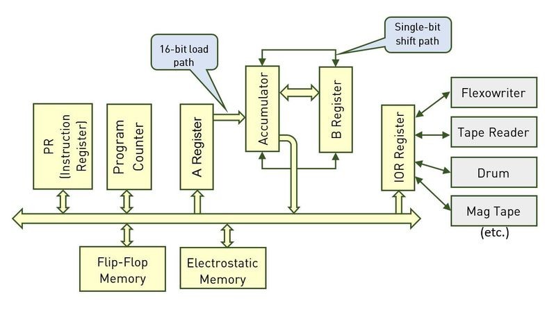
Figure 1: WW Programmer's View
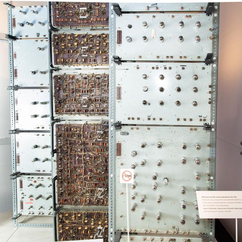
Whirlwind racks on display in Revolution. The revolutionary MIT Whirlwind computer used about 5,000 vacuum tubes and, in the mid-1950s, was among the most powerful computers in the world. Photo © Mark Richards.
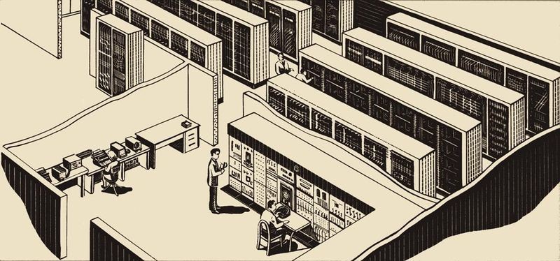
As a physical object, the Whirlwind computer was large. The computer itself occupied over 2,000 square feet in a room on the second floor of the Barta Building at MIT,1 with auxiliary drum storage equipment on the first floor and power-conditioning gear in the basement. The machine was not built to minimize floor space; the project leader, Jay Forrester, knew that reliability would be a key concern and wanted to ensure that every single component, cable and vacuum tube, was easy to access and repair. The machine was assembled in 98 racks2 in the second-floor computer room, with another 18 racks of indicators, switches, oscilloscopes, control knobs, etc. in the control room.
Three of these racks are on display in CHM’s Revolution exhibition. Let’s examine where those racks fit in the machine.
Here’s a floor plan of the second-floor Whirlwind computer room, as it was in 1951. Each rectangle represents one rack, with a letter-number functional identifier. Racks are arranged in five rows with a central aisle.
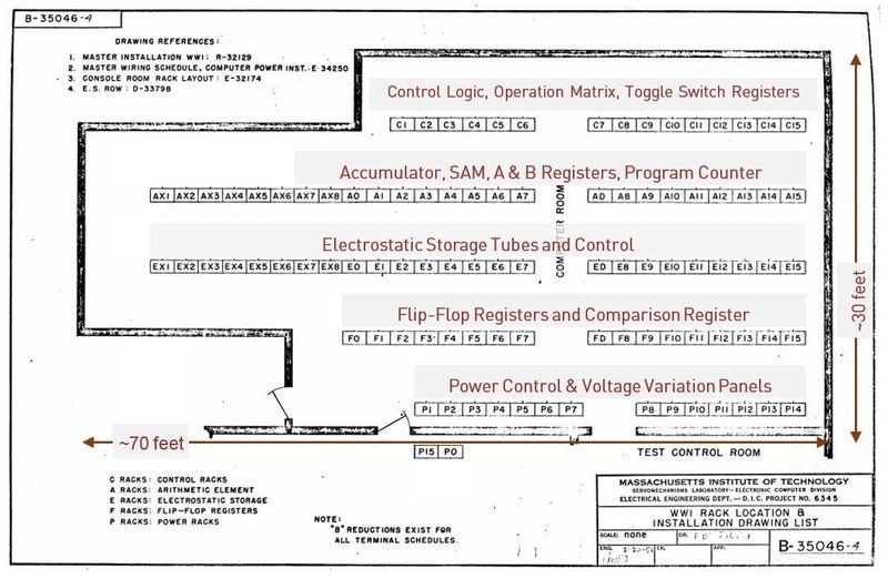
Figure 2: Barta Computer Room Floor Plan
Each row of racks was focused on a specific function:
Revolution contains three Whirlwind racks; the center and right-hand racks are identical, one facing forward, the other turned around backward.
The two identical racks each implement one bit of the main arithmetic unit for the machine.4 That is, each of these two identical racks hold eight distinct bits, plus associated logic—one bit of each of the Instruction Register, Program Counter, A Register, Accumulator, B Register, IO Register, Check Register, and Comparison Register. On the floor plan, there are 16 of these identical racks labeled A0 through A15, together providing the complete 16-bit arithmetic unit.
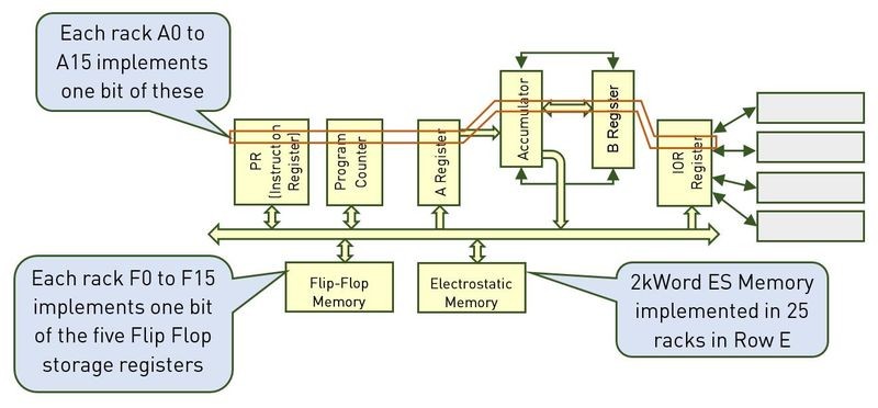
Figure 3: WW Physical Partitioning
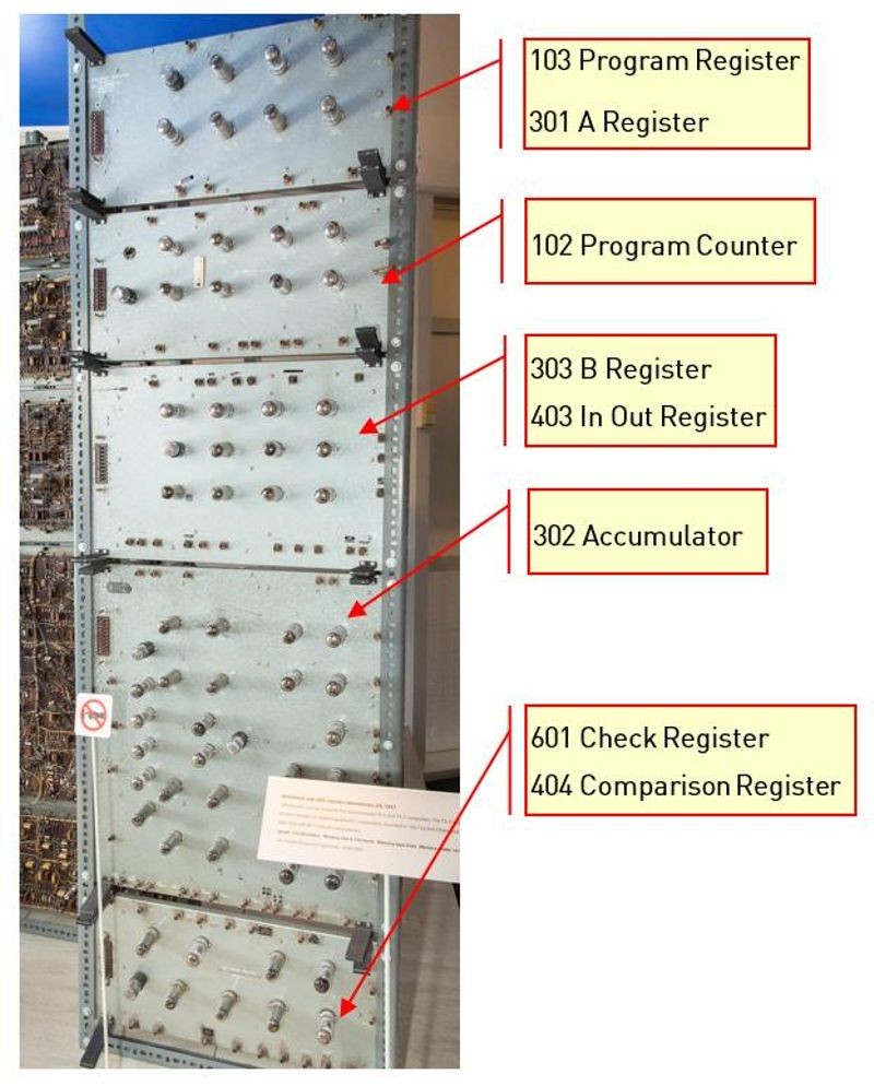
Figure 4: Panel Designation for Arithmetic Rack
To keep the design manageable, the Whirlwind team divided each rack into a series of panels, each with a specific function, roughly corresponding to blocks on the system block diagram. For the arithmetic racks, the panels are assigned as in Figure 4. Each panel has a name to describe its function (for example, “B Register”) and a three-digit block number that lines up with the system block diagrams. Each arithmetic rack contains one bit of storage plus all the associated logic for these units.5
Within the Arithmetic unit, the Accumulator panel (Block 302) is the most complex. This unit was responsible for the actual arithmetic—adding, subtracting, complementing, carrying, and shifting. The image reproduced in Figure 5, from the document Whirlwind I Computer Block Diagrams, shows what’s in the Accumulator panel.
The block diagram of the Whirlwind Accumulator panel shows a number of components:
The Accumulator panel has a total of 28 vacuum tubes to implement one bit, so the complete 16-bit Accumulator would have used 16 panels, or 448 vacuum tubes.
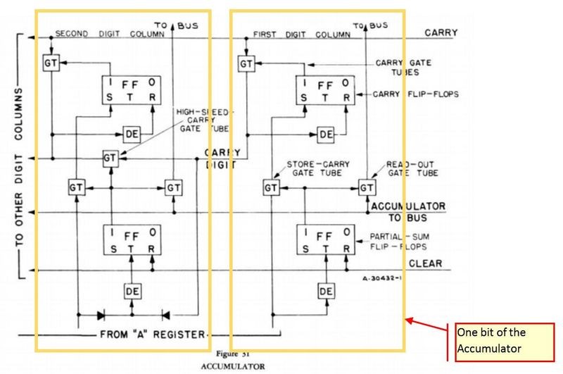
Figure 5: Accumulator panel (Block 302) in the Arithmetic unit.
The left-most Whirlwind rack on display in Revolution contains the “Test Storage,” a tiny amount memory implemented with vacuum tube flip-flops. This rack type was replicated sixteen times in the F Row on the floor plan to form five words of storage. The one rack on display implements five bits of storage, and was one rack from the F0-F15 row.
In spite of its small capacity, Test Storage was critical during the initial development and testing of Whirlwind, when the arithmetic unit was functional long before the electrostatic memory tubes were working.
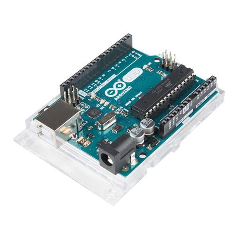
Arduino DIY microcontroller. Image: SparkFun Electronics.
Where would you find a computer comparable to Whirlwind today? The popular Arduino DIY microcontroller is not far off in capacity, although it’s many times faster.
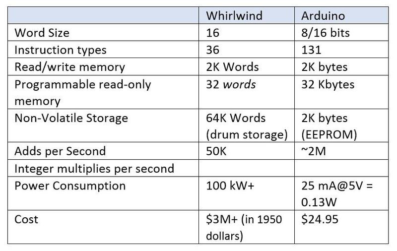
Figure 6: Datasheet comparison of Whirlwind and Arduino.
Whirlwind was a research machine with no direct commercial successor. But the machine still had an outsize impact on the overall development of computing:
Best of all, Whirlwind designers went on to seed the next generation of developments at MIT’s Lincoln Labs, MITRE, Digital Equipment Corporation, and others.
Not bad for a machine that could only fit five bits of storage in rack . . .
Look for a special holiday blog post from Guy on December 16—67 years to the day after the Whirlwind Jingle Bells program made its first public debut.